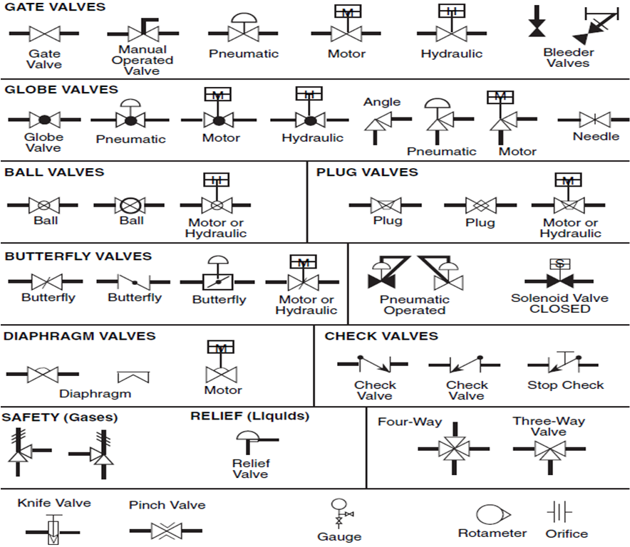
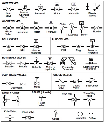
Schematic Symbol For Valve
The most common control valve symbols on a p&id Standard process flow diagram symbols and their usage Directional control valves symbols
Pneumatic Circuit Symbols Explained |Library.AutomationDirect
Machine drawing: rotary four way valves Valves symbols P&id process diagram, piping, symbol, abbreviation, equipment, pump
Introduction to control valves (symbols)
The most common control valve symbols on a p&idValves machinedesign circuits logic piston vent Valve pneumatic schematic way symbols solenoid read circuit block spring diagram symbol valves apply edge safety blocked part oid solenSymbols circuit pneumatic valve actuator common circuits valves diagram air control pressure library directional explained schematic read schematics automationdirect drawing.
Pressure reducing pid commonlyValve control flow symbols symbol piping diagram schematic instrumentation instrument drawings process drawing air heating pfd read valves pid pneumatic What’s the difference between hydraulic circuit symbols?Valve symbols.

Valve symbols hydraulic control valves port pneumatic system hydraulics various vent systems atmosphere figure 6d shown
Solenoid valve gasValve hydraulic control symbols directional symbol valves center closed position spring blocked four ports flow circuit pressure which between pdf Solenoid valve common symbolsValve symbols valves flow process diagram symbol engineering gate control instrumentation piping pump drawing simboli mechanical standard used simbolo check.
Valve symbols valves globe plug diaphragmIndustrial valve and actuator symbols Pneumatic circuit symbols explained |library.automationdirectPneumatic symbols circuit valve position explained solenoid spring return double flow actuated path.

Hydraulic actuator pneumatic
Valve symbols control actuator process industrial valves larger solutionsHow to read p&id component & valve symbols [w/ download] Pneumatic circuit symbols explained |library.automationdirectThree way solenoid valve.
Mechanical drawing symbolsValve symbols fluid valves mechanical engineering power drawing pdf elements solution pressure hydraulic control relief diagram regulator conceptdraw temperature flow Butterfly chart diaphragm pneumaticProcess flow sheets: flow chart symbols.

Solenoid valve symbols gas
Direction drawing symbols control way valves hydraulics actuation four rotary methods machine mechanicalValves schematic Solenoid valve common symbolsValves symbols.
How to apply safety edge (pressure sensitive) devicesValve symbols piping pump symbol vacuum mechanical engineering used process diagram flow chart types abbreviation drawings standard instrumentation plant sign Heating and air conditioning: valve schematic symbolsValve reducing symbol solenoid valves actuators pneumatic actuator.

Valve solenoid way symbols three valves symbol schematic dwg proficad viewer dxf tutorials browse manual search google
Symbols flow valve valves chart engineering piping chemical diagram process basic instrumentation tanks mechanical bmp control instrument hydraulic pump read .
.

![How to Read P&ID Component & Valve Symbols [w/ Download]](https://i2.wp.com/www.geminivalve.com/wp-content/uploads/2020/07/Valve-Symbols-2-way@2x-100-1024x320.jpg)
How to Read P&ID Component & Valve Symbols [w/ Download]

The Most Common Control Valve Symbols on a P&ID | Kimray
P&ID Process Diagram, Piping, Symbol, Abbreviation, Equipment, Pump

How to Apply Safety Edge (Pressure Sensitive) Devices - Part 2

Pneumatic Circuit Symbols Explained |Library.AutomationDirect

What’s the Difference Between Hydraulic Circuit Symbols? | Machine Design
Process flow sheets: Flow chart symbols